
Concealed Pulley Bevel Gear

This mechanism was the culmination of a quarter-long exploration into gears, pulleys, linkages cams, and mechanical motion. I designed and assembled a fully functional system that integrates a concealed pulley with 3D-printed bevel gears, using only hardware-based connections and press-fitting — no glue or adhesives.
This project combined laser cutting, 3D printing, and iterative prototyping to create a clean, precise form that emphasizes both functionality and craft.
The Process
MEDGI

Mapping, Educing, Disrupting, Gestalting, and Integrating
This was the process I followed to consider my original mechanism (the bevel gear), identify its form and function (mapping), its pleasure and pain points in use (educing), suggest possible alterations (disrupting), identifying how these changes affect the functionality (gestalting), and ultimately bringing it all together into a reworked mechanism. I followed this process three times, chaining each into the next, to arrive at my final design.
MEDG 1

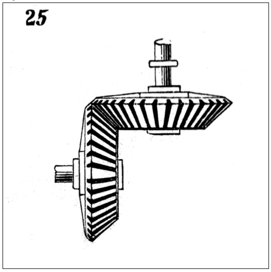
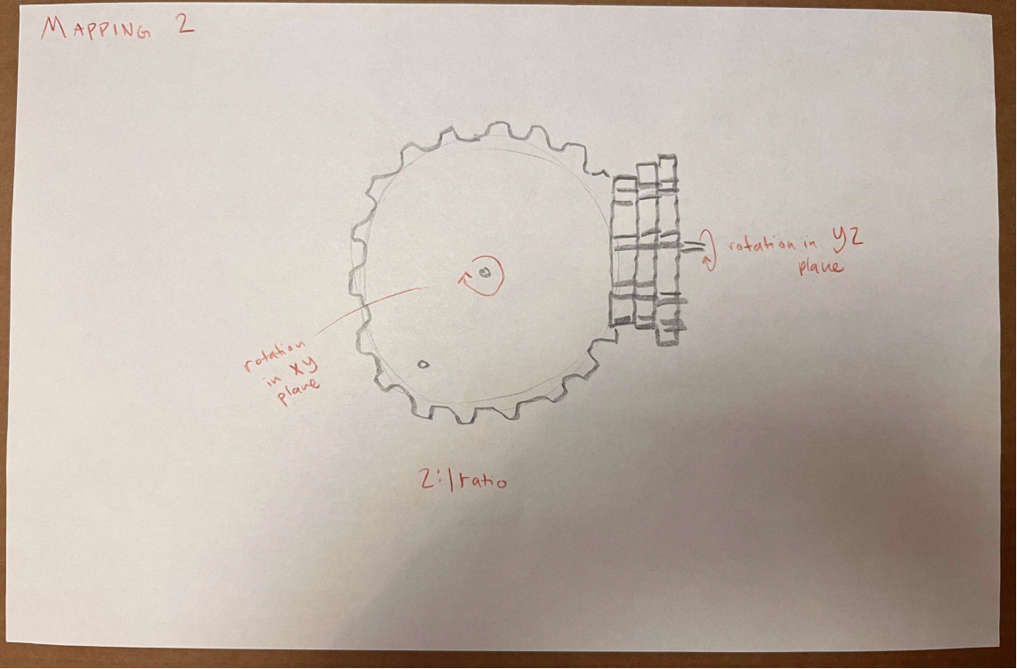
Mapping of Mechanism 25. This is what’s there.

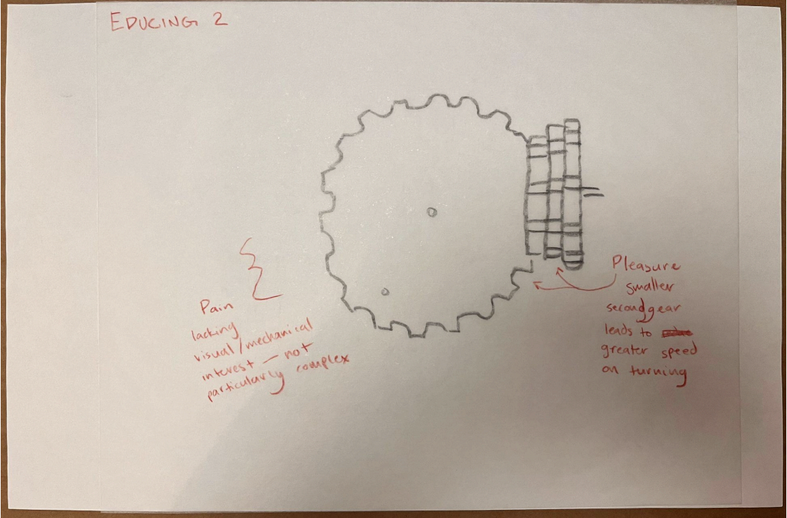
Educing Mechanism 25. These are pleasure and pain points.

Disrupting: What happens if I decrease the size of the bevel gear in the YZ plane?

MEDGI
Gestalting the disruption: The gear’s reduced size would cause it to rotate faster.
Integrating on paper:
Learning and reflections
This is where I started off — considering a bevel gear mechanism that transform rotary motion in the XY plane to rotary motion in the XZ plane:
MEDG 2

Mapping the prior MEDG’s gestalting. This is what’s there.
Educing: these are pleasure and pain points.

Mapping of Mechanism 25. This is what’s there.

Educing: these are pleasure and pain points.

Disrupting: What happens if I integrate a spatial pulley into the mechanism?
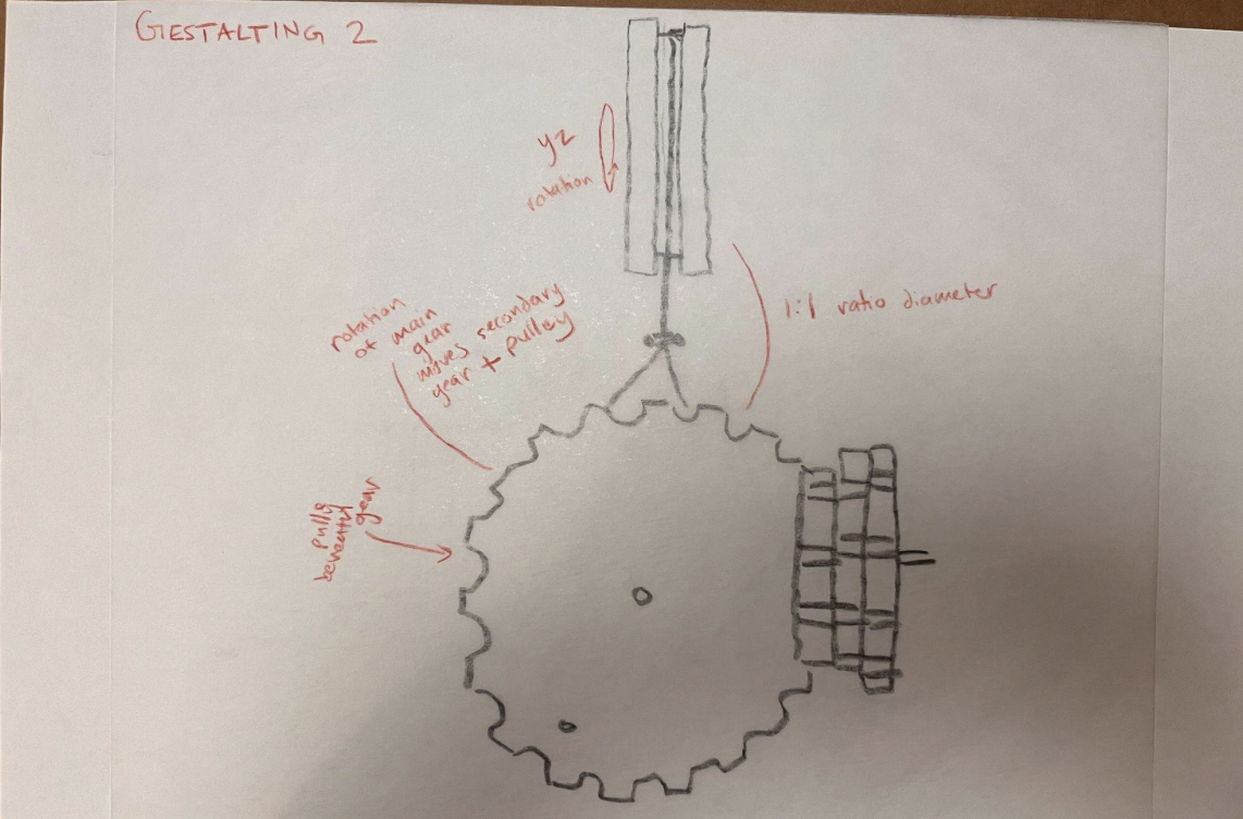
Gestalting: Integrating a pulley will add another rotation in the YZ plane.

Modeling and working towards final

Exploded view of a CAD model of my reworked mechanism, 1:2 scale

MEDG 3

Disrupting: What happens if I reduce the size of the YZ axis aspect of the pulley?

Gestalting the disruption: The pulley will now have an increased rate of rotation.

After three cycles of MEDG and extensive consideration, I arrived at the final design I wanted to integrate through prototyping, iteration, laser cutting and 3D printing. I began by creating a version of the newly revamped mechanism in cardboard.
The Prototype!
Process highlights:
Using the band saw and hand tools to precisely carve out 6 total gears for layering to emulate a bevel shape.
Gluing white paper atop functional pieces to call them to the foreground and highlight moving parts.
Using dowels as axes to allow rotational gear and pulley movements.
Engineering drawing of my reworked mechanism
Lessons learned:
The string used around the pulley lacks friction, causing slipping and preventing the pulley from moving in sync with the gears.
The smaller lateral gear should have its axis through a slot, not a point hole, to allow more flexibility and lubricate the motion of the gears.
The dowels that the rope passes through cause too much friction, also preventing the pulley’s rotation


The Beauty Shot
Process highlights:
Laser cutting the backboard with prepositioned, appropriately sized openings for press-fitting materials (no adhesives were permitted in the final iteration of this project)
Laser cutting the wheels of the pulley, as well as the supports for the pulley and the gears to be press-fit into the base
3D printing the bevel gears and the guide for the pulley belt to pass through
Working with hardware fasteners to secure gears and pulley and reduce friction around rotational axes
Improvements from prototype:
Replaced the string with an elastic band, and put hot glue on the side that contacted the wheel to increase tension and friction and aid in movement
Laser cut a slot into the piece supporting the lateral gear to prevent pressure and allow for smooth rotation
3D printed the guide for the pulley belt and sanded the inside, reducing unneccesary friction and promoting smooth pass-through

This project was the culmination of a quarters worth of work considering, replicating, and altering classic mechanisms. Over the course of my efforts on this project as well as the class as a whole, I became much more comfortable using basic prototyping techniques including work with cardboard for rapid iteration, as well as with legitimate production skills such as familiarity with the laser cutter, machinery such as saws and sanders, 3D modeling and printing, and constructing engineering drawings. However, the most important skill I took away was the ability to consider an everyday, commonplace object, identify what was and wasn’t working for me, and iteratively work towards tangibke changes to implement for an improved product.