


The Head
The first step of manufacturing the head was casting — in the Stanford PRL, we use sand casting. I used graphite powder on the pattern board to ensure smooth separation, then tamped down the sand around my pattern, ensuring minimal breakage for a smooth pour.
After pouring, I used a dremel to take off the roughest layer of material, then continued with progressive hand sanding until I reached a finish I was happy with. For this project, I decided that a mirror finish wouldn’t be appropriate, since it would inevitably scratch and dull with use. Instead, I went for a duller sheen to maintain the aesthetics of the tool without impacting its functionality. After hand finishing, I used a polishing wheel to buff the piece.
After finishing the head, I used specially prepared soft jaws to secure it to the mill, and milled holes into each circular face (left, right, and bottom), adhering to the specified diameter and depth provided in the engineering drawings. I then tapped both holes, two using the mill and the other by hand, to produce smooth threading.
The final step for the head of the hammer was to use the CNC machine to engrave a phrase of my choice (note that I chose to leave the engraving face with its cast finish to create visual interest). Working with the limited character space, I chose to write “it is all nails” to play off the phrase “when you have a hammer, everything looks like a nail”.
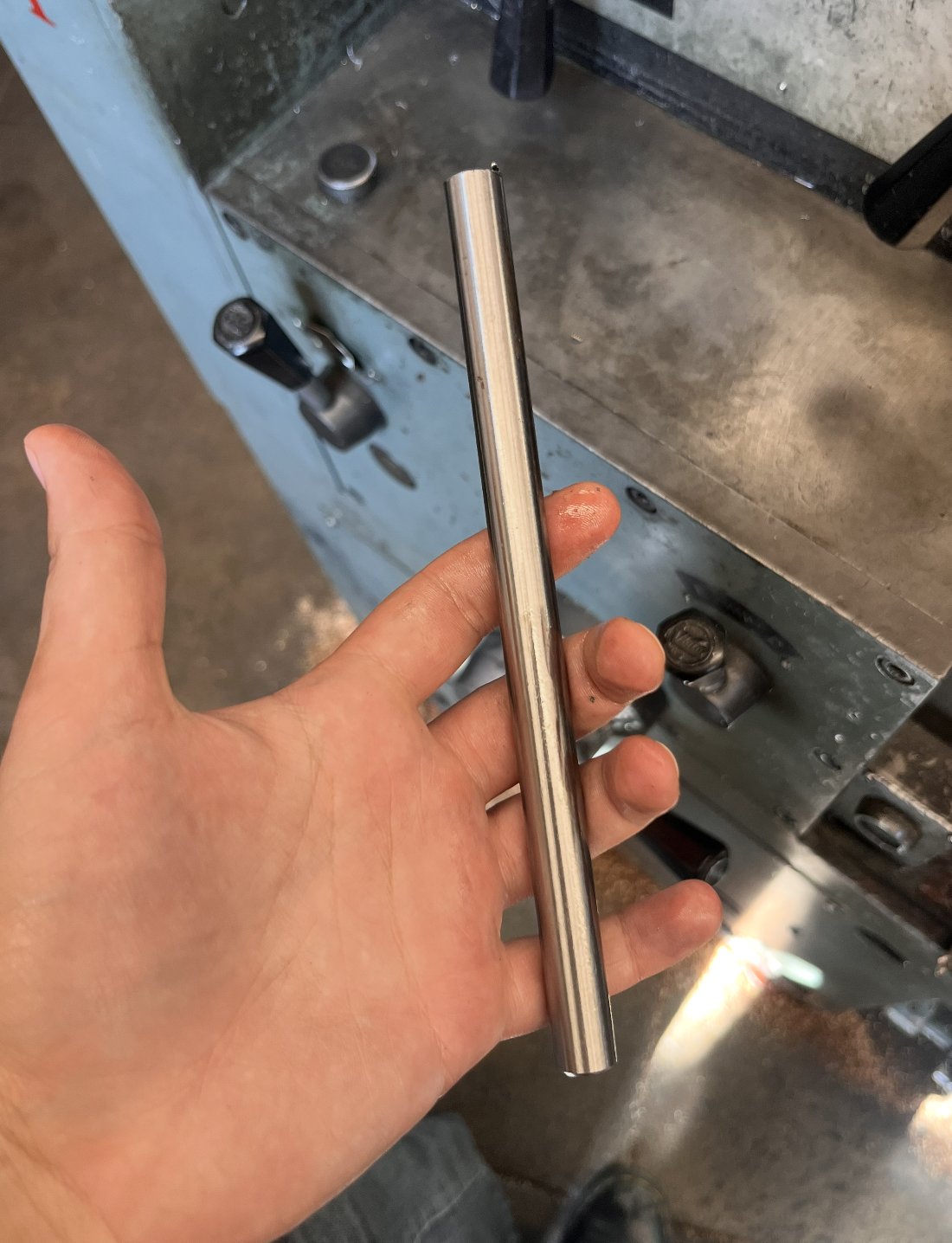
The Handle
The handle was made entirely on the lathe — the stock was already the appropriate diameter, so I used a parting tool to cut it to length, then created a small chamfer on the base, and drilled out and tapped a hole on the side of the handle that would attach to the hammer. I chose to preserve the original finish of this material rather than further sanding it, since it was already well matched to the finishing I had done on the head.

The Machined Hammer
The Stanford ME department provided me with technical drawings outlining strict tolerances — failing to adhere to these numbers by any more than an tenth of an inch was unacceptable. Using these directives, I set out to manufacture the constituent parts of the hammer: the two plastic caps, the bronze cast head, and the aluminum rod handle.

The Caps

Takeaways


To make the caps, I used the lathe to cut down plastic stock to the specified diameter — on the left is a higher density material, while the right is softer, giving the hammer a range of capability. After cutting to size, I added a small chamfer to the outside edge, then created a small hole on the lathe and heat set a threaded insert into each.
Assembly

I used small pieces of threaded rod inserted between each loose component to secure the hammer together — by adhering strictly to the tolerances outlined in the engineering drawings, I ensured that all joined faces were concentric and transitioned smoothly.
This project strengthened my ability to read, interpret, and execute technical drawings with tight tolerances. Working through sand casting, turning, milling, tapping, and joining operations taught me how to plan a machining sequence, account for stock removal, and adapt to unexpected material behavior. It also helped me build confidence navigating a fast-paced shop environment and collaborating around shared tools and workflows.